
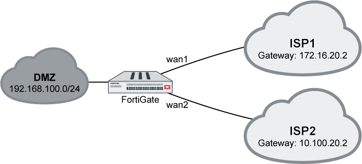
This recipe provides an example of how to start using SD-WAN for load balancing and redundancy.
In this example, two ISP internet connections (wan1 and wan2) use SD-WAN to balance traffic between them at 50% each.
To configure SD-WAN using the GUI:
- On the FortiGate, enable SD-WAN and add interfaces wan1 and wan2 as members:
- Go to Network > SD-WAN.
- Set the Status to Enable.
- Click the plus icon to add members, using the ISPs’ proper gateways for each member.
 If IPv6 visibility is enabled in the GUI, an IPv6 gateway can also be added for each member. See Feature visibility for details.
 - Click Apply to save your settings.
- Create a static route with virtual-wan-link enabled:
- Go to Network > Static Routes.
- Click Create New. The New Static Route page opens.
- From the Interface drop-down list, select SD-WAN.
- Click OK to save your changes.
- Create a firewall policy to allow the traffic:
- Go to Policy & Objects > IPv4 Policy.
- Click Create New. The New Policy page opens.
- For the Incoming Interface, select DMZ.
- For the Outgoing Interface, select SD-WAN.
- Configure the remaining settings as needed, then click OK to create the policy.
To configure SD-WAN using the CLI:
- On the FortiGate, configure the wan1 and wan2 interfaces:config system interface edit “wan1” set alias to_ISP1 set ip 172.16.20.1 255.255.255.0 next edit “wan2” set alias to_ISP2 set ip 10.100.20.1 255.255.255.0 next end
- Enable SD-WAN and add the interfaces as members:config system virtual-wan-link set status enable config members edit 1 set interface “wan1” set gateway 172.16.20.2 next edit 2 set interface “wan2” set gateway 10.100.20.2 next end end
- Configure a static route:config router static edit 1 set distance 1 set virtual-wan-link enable next end
- Configure a firewall policy:config firewall policy edit 2 set name “VWL” set srcintf “dmz” set dstintf “virtual-wan-link” set srcaddr “all” set dstaddr “all” set action accept set schedule “always” set service “ALL” set nat enable next end
- Use a diagnose command to check the state of the SD-WAN:# diagnose sys virtual-wan-link member Member(1): interface: wan1, gateway: 172.16.20.2, priority: 0, weight: 0 Member(2): interface: wan2, gateway: 10.100.20.2, priority: 0, weight: 0
Using DHCP interface
This recipe provides a sample configuration for customer using the DHCP interface as SD-WAN members. SD-WAN members can be all static IP interfaces, all DHCP interfaces, or a mix of both IP and DHCP interfaces.
In this example, a customer who has two ISP internet connections: wan1 and wan2. wan1 is a DHCP interface and wan2 is a static IP address interface.
Sample topology
To configure DHCP interface on the GUI:
- Enable SD-WAN and add wan1 and wan2 as SD-WAN members.
- Go to Network > SD-WAN and ensure Status is Enable.
- In the SD-WAN Interface Members section, click the + button and add two members: wan1 and wan2.
- For the static IP member, enter the Gateway address.
- For the DHCP member, do not change the Gateway.
- Click Apply.
- Create static route and enable virtual-wan-link.
- Go to Network > Static Routes and click Create New.
- Click the Interface dropdown list and select SD-WAN.
- Click OK.
- Create policy for this traffic.
- Go to Policy & Objects > IPv4 Policy and click Create New.
- For the Incoming Interface, select dmz.
- For the Outgoing Interface, select SD-WAN
- Configure other options as needed.
- Click OK.
Outgoing traffic is balanced between wan1 and wan2 at about 50% each.
To configure the interface on the CLI:
config system interface
    edit "wan1"
        set alias to_ISP1
        set mode dhcp
    next
    edit "wan2"
        set alias to_ISP2
        set ip 10.100.20.1 255.255.255.0
    next
end
To configure SD-WAN on the CLI:
config system virtual-wan-link
    set status enable
    config members
        edit 1
            set interface "wan1"
        next
        edit 2
            set interface "wan2"
            set gateway 10.100.20.2
        next
    end
end
To configure static route on the CLI:
config router static
    edit 1
        set distance 1
        set virtual-wan-link enable
    next
end
To configure firewall policy on the CLI:
config firewall policy
    edit 2
        set name "VWL"
        set srcintf "dmz"
        set dstintf "virtual-wan-link"
        set srcaddr "all"
        set dstaddr "all"
        set action accept
        set schedule "always"
        set service "ALL"
        set nat enable
    next
end
To use the diagnose command to check SD-WAN state:
# diagnose sys virtual-wan-link member
Member(1): interface: wan1, gateway: 172.16.20.2, priority: 0, weight: 0
Member(2): interface: wan2, gateway: 10.100.20.2, priority: 0, weight: 0
Implicit rule
SD-WAN supports five types of implicit rules (load-balance mode):
- Source IP (CLI command:
source-ip-based): SD-WAN will load balance the traffic equally among its members according to a hash algorithm based on the source IP addresses. - Session (
weight-based): SD-WAN will load balance the traffic according to the session numbers ratio among its members. - Spillover (
usage-based): SD-WAN will use the first member until the bandwidth reaches its limit, then use the second, and so on. - Source-Destination IP (
source-dest-ip-based): SD-WAN will load balance the traffic equally among its members according to a hash algorithm based on both the source and destination IP addresses. - Volume (
measured-volume-based): SD-WAN will load balance the traffic according to the bandwidth ratio among its members.
Examples
The following four examples demonstrate how to use the implicit rules (load-balance mode).
Example 1
Outgoing traffic is equally balanced between wan1 and wan2, using source-ip-based or source-dest-ip-based mode.
Using the GUI:
- On the FortiGate, enable SD-WAN and add wan1 and wan2 as SD-WAN members, then add a policy and static route. See Creating the SD-WAN interface for details.
- Go to Network > SD-WAN Rules.
- Edit the sd-wan rule (the last default rule).
- For the Load Balancing Algorithm, select either Source IP or Source-Destination IP.

- Click OK.
Using the CLI:
- Enable SD-WAN and add wan1 and wan2 as SD-WAN members, then add a policy and static route. See Creating the SD-WAN interface for details.
- Set the load balancing algorithm:Source IP based:config system virtual-wan-link set load-balance-mode source-ip-based endSource-Destination IP based:config system virtual-wan-link set load-balance-mode source-dest-ip-based end
Example 2
Outgoing traffic is balanced between wan1 and wan2 with a customized ratio, using weight-based mode: wan1 runs 80% of the sessions, and wan2 runs 20% of the sessions.
Using the GUI:
- Go to Network > SD-WAN Rules.
- Edit the sd-wan rule (the last default rule).
- For the Load Balancing Algorithm, select Sessions.
- Enter 80 in the wan1 field, and 20 in the wan2 field.

- Click OK.
Using the CLI:
config system virtual-wan-link
    set load-balance-mode weight-based
    config members
        edit 1
            set interface "wan1"
            set weight 80
        next
        edit 2
            set interface "wan2"
            set weight 20
        next
    end
end
Example 3
Outgoing traffic is balanced between wan1 and wan2 with a customized ratio, using measured-volume-based mode: wan1 runs 80% of the volume, and wan2 runs 20% of the volume.
Using the GUI:
- Go to Network > SD-WAN Rules.
- Edit the sd-wan rule (the last default rule).
- For the Load Balancing Algorithm, select Volume.
- Enter 80 in the wan1 field, and 20 in the wan2 field.
- Click OK.
Using the CLI:
config system virtual-wan-link
    set load-balance-mode measured-volume-based
    config members
        edit 1
            set interface "wan1"
            set volume-ratio 80
        next
        edit 2
            set interface "wan2"
            set volume-ratio 20
        next
    end
end
Example 4
Load balancing can be used to reduce costs when internet connections are charged at different rates. For example, if wan2 charges based on volume usage and wan1 charges a fixed monthly fee, we can use wan1 at its maximum bandwidth, and use wan2 for overflow.
In this example, wan1’s bandwidth is 10Mbps down and 2Mbps up. Traffic will use wan1 until it reaches its spillover limit, then it will start to use wan2. Note that auto?asic?offload must be disabled in the firewall policy.
Using the GUI:
- On the FortiGate, enable SD-WAN and add wan1 and wan2 as SD-WAN members, then add a policy and static route. See Creating the SD-WAN interface for details.
- Go to Network > SD-WAN Rules.
- Edit the sd-wan rule (the last default rule).
- For the Load Balancing Algorithm, select Spillover.
- Enter 10000 in the wan1 Ingress Spillover Threshold field, and 2000 in the wan1 Egress Spillover Threshold field.

- Click OK.
Using the CLI:
config system virtual-wan-link
    set load-balance-mode usage-based
    config members
        edit 1
            set interface "wan1"
            set spillover-threshold 2000
            set ingress-spillover-threshold 10000
        next
    end
end
Factory default health checks
There are five predefined performance SLA profiles for newly created VDOMs or factory reset FortiGate devices:
- AWS
- FortiGuard
- Gmail
- Google Search
- Office 365
You can view and configure the SLA profiles in Network > Performance SLA.

After configuring a health check, you will be able to view packet loss, latency, and jitter data for the SLA profiles. If a value is colored red, it means that it failed to meet the SLA requirements.

To configure the performance SLA profiles in the CLI:
config system virtual-wan-link
    config health-check
        edit "Default_Office_365"
            set server "www.office.com"
            set protocol http
            set interval 1000
            set recoverytime 10
            config sla
                edit 1
                    set latency-threshold 250
                    set jitter-threshold 50
                    set packetloss-threshold 5
                next
            end
        next
        edit "Default_Gmail"
            set server "gmail.com"
            set interval 1000
            set recoverytime 10
            config sla
                edit 1
                    set latency-threshold 250
                    set jitter-threshold 50
                    set packetloss-threshold 2
                next
            end
        next
        edit "Default_AWS"
            set server "aws.amazon.com"
            set protocol http
            set interval 1000
            set recoverytime 10
            config sla
                edit 1
                    set latency-threshold 250
                    set jitter-threshold 50
                    set packetloss-threshold 5
                next
            end
        next
        edit "Default_Google Search"
            set server "www.google.com"
            set protocol http
            set interval 1000
            set recoverytime 10
            config sla
                edit 1
                    set latency-threshold 250
                    set jitter-threshold 50
                    set packetloss-threshold 5
                next
            end
        next
        edit "Default_FortiGuard"
            set server "fortiguard.com"
            set protocol http
            set interval 1000
            set recoverytime 10
            config sla
                edit 1
                    set latency-threshold 250
                    set jitter-threshold 50
                    set packetloss-threshold 5
                next
            end
        next
    end
end
